post

How To: End-to-End SnapProtect Storage Policy Creation

The example I’m going to give here is for an environment that is already configured but has storage controllers that are not configured as NAS iData Agents for backup or any volumes on those controllers. In this environment the controller I’m enabling backups on is the secondary storage tier which is already a snapvault destination so it is in the Array Manager for SnapProtect. This environment requires new NetApp aggregates to be added as resource pools as new volumes and data have been assigned to the aggregates. The process involves working with SnapProtect, NetApp Management Console (DFM) and the NetApp storage controllers.

Enable backups on a controller within SnapProtect:

Enable Accounts

Before you begin log onto the controller and ensure the login account you require has access to the controller. To do this open a SSH session to the controller and use the following command:

#useradmin user list

If the account used by SnapProtect doesn’t exist then you’ll need to add it as an administrator. Below is a snapshot from a controller where it is added and also a controller where it’s not.

SnapProtect End to End Step 1

SnapProtect End to End Step 2

You can add the account via the command line or via the web console. In this instance I added the account via the console. In System Manager go to Configuration -> Local Users and Groups -> Users and click Create. Enter the required details and click Create.

SnapProtect End to End Step 3

Once completed you can re-run the command from the CLI to ensure that the account appears Read More

post

How to: Present iSCSI storage from a NetApp vfiler (7-Mode)

As part of a recent data migration I had to enable a vfiler to allow iSCSI traffic as a number of virtual machines in the environment require block storage for clustering reasons. The vfiler already presents via NFS and iSCSI. As this is a test environment I’ve decided to put iSCSI on the same link as the NFS and CIFS. I know this is not normal best practice but given that the vLANs are already in place and that this is a test environment I decided to use the same IP address range. The servers accessing the iSCSI LUNs don’t have access to CIFS or to any NFS mounts already so there should be no traffic cross-over. So onto the steps to set it up:

Step 1: Allow iscsi protocol and RSH on vfiler (at vfiler0)

Check the status of the vfiler using the command

vfiler status -a tenant_vfiler
tenant_vfiler running
 ipspace: tenant_vfiler_NFS_CIFS
 IP address: 192.168.2.1 [a1a-107]
 IP address: 192.168.2.2 [a1a-107]
 Path: /vol/tenant_vfiler_vol0 [/etc]
 Path: /vol/nfs03
 Path: /vol/nfs04
 Path: /vol/nfs02
 Path: /vol/nfs01
 Path: /vol/cifs01
 Path: /vol/iso01
 Path: /vol/iscsi_test
 UUID: 93c62e36-4e76-11e4-8721-123478563412
 Protocols allowed: 7
Disallowed: proto=rsh
 Allowed: proto=ssh
 Allowed: proto=nfs
 Allowed: proto=cifs
Disallowed: proto=iscsi
 Allowed: proto=ftp
 Allowed: proto=http
 Protocols disallowed: 2

Next run the command:

vfiler allow tenant_vfiler proto=iscsi
vfiler allow tenant_vfiler proto=rsh

Step 2: Start iSCSI protocol on vfiler (at apaubmwvfi01)

vfiler context tenant_vfiler
iscsi start

Step 3: Create a new volume at vfiler0

vfiler context vfiler0
vol create iscsi_test_vol -s 20g

Step 4: Migrate the volume to apaubmwvfi01 and log into the vfielr to check the volume status

vfiler add tenant_vfiler /vol/iscsi_test
vfiler context tenant_vfiler
vol status

Step 5: Set priv advanced and modify the exports to the correct settings as below

To modify the exports read the current /exports and write it back. Once done run the exportsfs -av command to push the changes out

rdfile /vol/tenant_vfiler_vol0/etc/exports
/vol/nfs01 -sec=sys,rw=192.168.1.0/24,anon=0
/vol/nfs02 -sec=sys,rw=192.168.1.0/24,anon=0
/vol/nfs03 -sec=sys,rw=192.168.1.0/24,anon=0
/vol/nfs04 -sec=sys,rw=192.168.1.0/24,anon=0
/vol/iso01 -sec=sys,rw=192.168.1.0/24,anon=0
/vol/iscsi_test -sec=sys,rw=192.168.1.0/24,anon=0
vfiler run tenant_vfiler exportfs -av

Step 6: Create a lun from the volume (iscsi_test)

vfiler run tenant_vfiler lun create -s 10g -t windows2008 /vol/iscsi_test/iscsi_lun

Step 7: Change filer and run lun show

lun_show

Step 8: Verify iSCSI network within VMware has been assigned to the VM
iSCSI network
Step 9: Enable iSCSI Initiator – grab the iqn

iSCSI initiator iqn

Step 10: Create an igroup with the iqn of the server

igroup create -t Windows2008 ds_iscsi 
igroup add ds_iscsi iqn.1991-05.com.microsoft:microsoft:server.domain.com

Step 11: map the lun to the group name

map_lun_to_group

Step 12: run lun show -m to check the mapping

lun_show_mapping

Step 13: Run a quick connect to the IP address of the controller

iscsi_quick_connect

And now your disk should appear in the disk manager on the server. It’s not too different to setting up a normal iSCSI connection but RSH must be enabled otherwise it can’t tunnel the iSCSI  request to the vfiler iqn target.

NetApp 7-Mode MetroCluster Disaster Recovery – Part 3

This is the last of the 3-part post about MetroCluster failover procedure. This section covers the giveback process and also a note about a final review. The other sections of this blog post can be found here:

  1. NetApp 7-Mode MetroCluster Disaster Recovery – Part 1
  2. NetApp 7-Mode MetroCluster Disaster Recovery – Part 2

Test Case 4 – Virtual Infrastructure Health Check

This test case covers a virtual infrastructure system check, not only to get an insight into the current status of the system but to also compare against the outcomes from test case 1.

4.1 – Log into vCenter  using the desktop client or web client. Expand the virtual data center and verify all SiteB ESXi hosts are online

4.2 – Log onto NetApp onCommand System Manager. Select primary storage controller and open application

4.3 – Expand SiteA/SiteB and expand primary storage controller, select Storage and Volumes. Volumes should all appear with online status

4.4 – Log into Solarwinds – Check the events from the last 2 hours and take note of all devices from Node List which are currently red

Read More

post

NetApp 7-Mode MetroCluster Disaster Recovery – Part 2

This is the part 2 of the 3-part post about MetroCluster failover procedure. This section covers the giveback process and also a note about a final review. The other sections of this blog post can be found here:

  1. NetApp 7-Mode MetroCluster Disaster Recovery – Part 1
  2. NetApp 7-Mode MetroCluster Disaster Recovery – Part 3

The planning and environment checks have take place and now it’s time to execution day. I’ll go through the process here of how the test cases were followed during testing itself. Please note that Site A (SiteA) is the site where the shutdown is taking place. Site B (SiteB) is the failover site for the purpose of this test.

Test Case 1 – Virtual Infrastructure Health Check

This is a health check of all the major components before beginning the execution of the physical shutdown

1.1 – Log into Cisco UCS Manager on both sites using an admin account.

1.2 – Select the Servers tab, and expand Servers -> Service Profiles -> root -> Sub-Organizations -> <SiteName>. List of blades installed in relevant environment will appear here

1.3 – Verify the Overall status. All blades appear with Ok status. Carry on with the next

1.4 – Log into vCenter using desktop client or web client. Select the vCenter server name at top of tree, select Alarms in right-hand pane and select triggered alarms. No alarms should appear

1.5 – Verify all ESX hosts are online and not in maintenance mode

1.7 – Log onto NetApp onCommand System Manager. Select SiteA controller and open application

1.8 – Expand SiteA/SiteB and expand both controllers, select Storage and Volumes. Verify that all volumes are online

1.9 – Launch Fabric MetroCluster Data Collector (FMC_DC) and verify that the configured node is ok. The pre-configured FMC_DC object returns green – this means that all links are health and takeover can be initiated

DR failover Metrocluster FMDC Read More

post

NetApp 7-Mode MetroCluster Disaster Recovery – Part 1

Recently I had the honour of performing a NetApp 7-Mode MetroCluster DR Test. After my previous outing which can be read in its full gory details on another blog post I was suitably apprehensive about performing the test once again. Following the last test I worked with NetApp Support to find a root cause of the DR failure. The final synopsis is that it was due to the Service Processor being online while the DR site was down which caused hardware support to kick in automatically. This meant that a takeover was already running when the ‘cf forcetakeover -d’ command was issues. If the Service Processor is online for even a fraction of a second longer than the controller is it will initiate a takeover. Local NetApp engineers confirmed this was the case thanks to another customer suffering a similar issue and they performed multiple tests both with the Service Processor connected and disconnect. Only those tests that had the Service Processor disconnected were successful. However it wasn’t just the Service Processor. The DR procedure that I followed was not suitable for the test. WARNING: DO NOT USE TR-3788 FROM NETAPP AS THE GUIDELINE FOR FULL SITE DR TESTING. You’ll be in a world of pain if you do.

I had intended on this being just one blog post but it escalated quickly and had to be broken out. The first post is around the overview of steps followed and the health check steps carried out in advance. Part 2 covers the physical kit shutdown and the failover process. Part 3 goes into detail around the giveback process and some things that were noted during the DR test. To access the other parts of the post quickly you can use the links below.

  1. NetApp 7-Mode MetroCluster Disaster Recovery – Part 2
  2. NetApp 7-Mode MetroCluster Disaster Recovery – Part 3

Read More

post

NetApp Metrocluster DR test – tears, fears and joys

Edit: I have since completed a successful  Metrocluster Failover Test and it is documented in full in the following blog posts:

  1. NetApp 7-Mode MetroCluster Disaster Recovery – Part 1
  2. NetApp 7-Mode MetroCluster Disaster Recovery – Part 2
  3. NetApp 7-Mode MetroCluster Disaster Recovery – Part 3


Just before the Xmas break I had to perform a Metrocluster DR test. I don’t know why all DR tests need to be done just before a holiday period, it always seems to happen that way. Actually I do know but it doesn’t make the run up to the holidays any more comfortable for an IT engineer. Before I began the DR test I had a fairly OK knowledge of how MetroCluster worked but afterwards it’s definitely vastly improved. If you want to learn how MetroCluster works and how it can be fixed I’d recommend breaking your environment and work with NetApp support to fix it again. Make sure to put aside quite a bit of time so that you can get everything working again and your learning experience will be complete. (You may have problems convincing your boss to let you break your environment though). I haven’t worked with MetroCluster before so while I understood how it worked and what it could do I really didn’t understand the ins-and-outs and how it is different to a normal 7-Mode HA-cluster. The short version is that it’s not all that different but it is far more complex when it comes to takeovers and givebacks and just a bit more sensitive also. During my DR test I went from a test to an actual DR and infrastructure fix. Despite the problems we faced the data management and availability was rock solid and we suffered absolutely no data loss.

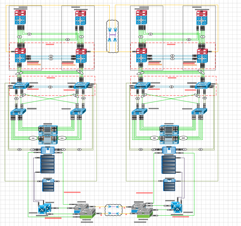
I won’t go deeply into what MetroCluster is and how it works here, I may cover that in a separate blog post, but the key thing to be aware of is that the aggregates are classed as Plexes and use SyncMirror to ensure that all writes in a primary Plex gets synchronously written to the secondary Plex so that all data exists in to places. SyncMirror differs from SnapMirror by synchronizing the aggregrates whereas SnapMirror occurs at the volume level. MetroCluster itself is classed as a disaster avoidance system and satisfied this by having multiple copies of synchronised data on different sites. The MetroCluster in our environment is part of a larger Flexpod environment which includes fully redundant Cisco Nexus switches, Cisco UCS chassis and blades and a back-end dark fibre network between sites. A 10,000 foot view of the environment looks something like the below diagram and I think you can agree that there are a lot of moving parts here.

metro cluster Infrastructure overview

So what exactly happened during the DR test and why did I lose a storage controller? Well I can out my hand up for my part in the failure and the other part comes down to NetApp documentation which is not clear as to what operations needs to be performed and in what sequence. As I’ll discuss later there’s quite a need for them to update their documentation on MetroCluster testing. The main purpose of this post is not to criticise MetroCluster but for me to highlight the mistakes that I made and how they contributed to the failure that occurred and what I would do differently in the future. It’s more of a warning for others to not make the same mistakes I did. Truth be told if the failure occurred on something that wasn’t a MetroCluster I may have been in real trouble and worst of all lost some production data. Thankfully MetroCluster jumped to my rescue on this front.  Read More